Welcome to My CAD 2 Portfolio
|
This portfolio covers the content and the many broad concepts and topics of Computer Aided Drafting, specifically at a more advanced level. It will cover everything from hand-drawn mechanical drafting down to automated 2D and 3D CAD software design.
|
Introduction
CAD 2 as a course continues the development of mechanical drawing skills using drafting tools and techniques. However, Students will work extensively with AutoCAD and OnShape for both 2D and 3D CAD software design. In addition to just geometric construction and orthographic projection views, other styles and instruction such as section views, multiviews, auxiliaries and exploded assembly drawings will be provided on these higher level educational programs along with hands-on design experience with these CAD software systems.
Hand-Drawn Mechanical Drafting
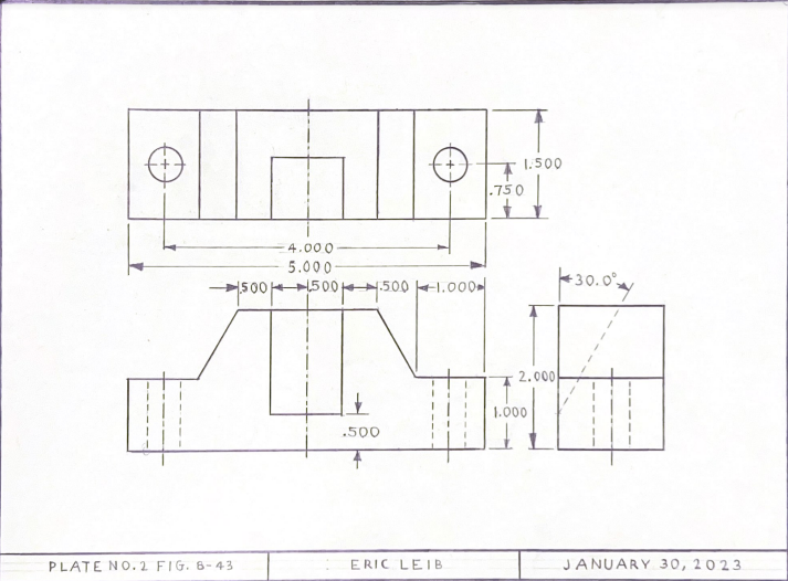
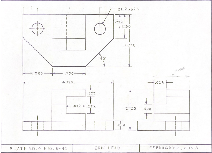
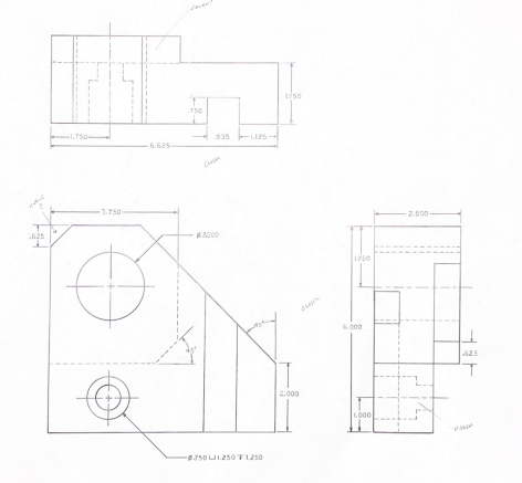
This section will consist strictly of hand-drawn mechanical drawings. Although mechanical drafting is a somewhat outdated drafting process, it is still a necessary practice for beginning drafters so that a solid understanding of drafting concepts is established and also so that the ability to read and interpret drawings/blueprints is acquired earlier on in the learning process, preferably before advancing into using Computer-Aided Drafting software systems.
|
Plate 2 - Fig 8-43 Adjustor Block-Orthographic |
|
Plate 4 - Fig 8-45 Flipper Dog-Orthographic |
|
Plate 5 - Fig 8-46 Guide Base-Orthographic |
Exploded Isometric Drawings
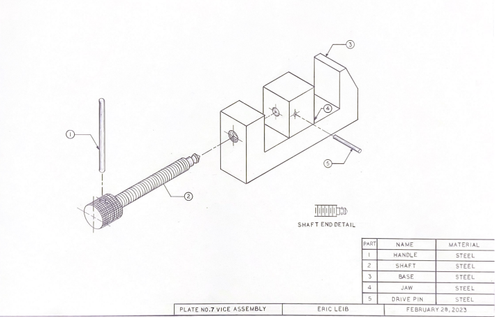
Isometric drawings display the common method of isometric projection for visually representing three-dimensional objects in both technical and engineering drawings. Using isometric projections is ideal for showing measurements and how multiple components fit together.
|
Plate 7 - Isometric Exploded Assembly for Tool Makers Vise |
AutoCAD: Single View Drawings
Single-view drawings attempt to picture an object or space as we normally see it in reality by picturing only the most prominent view and highlighting important notes, dimensions, and features of that object.
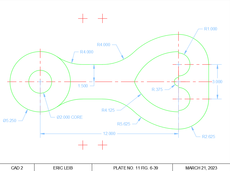
Plate 11 - Fig 6-39 Locomotive Truck Swing Link-Single View with Dimensions. Scale 1:2.
|
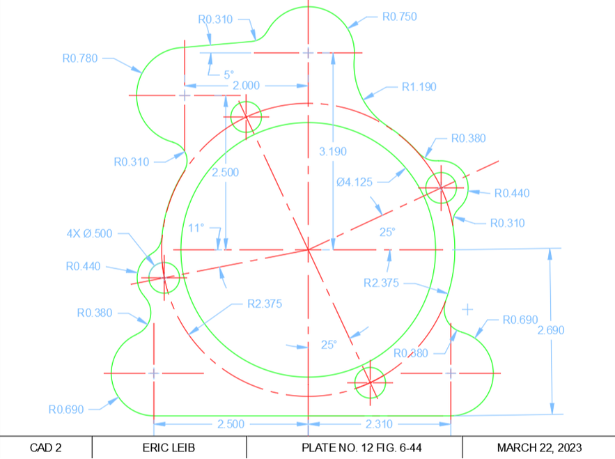
Plate 12 - Fig 6-44 Buick Rear Transmission Gasket-Single View with Dimensions.
|
AutoCAD: Orthographic Projection (Multiview) View Drawings
Orthographic projection views represent a 3D object by using 2D views of the front, top, and right side of an object. Typically, assembly drawings will also contain these multiview drawings for each part involved within the assembly itself if each part is too large to fit onto one drawing alone.
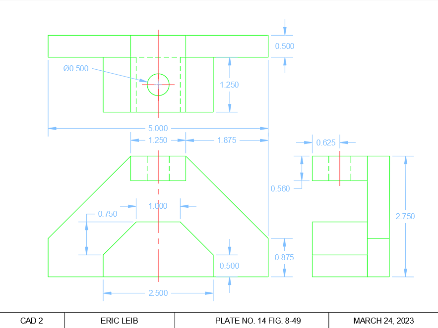
Plate 14 - Fig 8-49 Jig Block-Orthographic with Projection with Dimensions
|
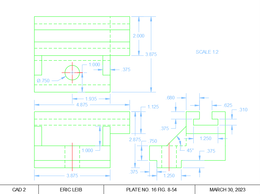
Plate 16 - Fig 8-54 Tool Post Block-Orthographic Projection with Dimensions
|
AutoCAD: Section-View Drawings
A section view is a view used on a drawing to show an area or hidden part within or behind an object by cutting away or removing some of that object. The cut line is called a “cutting plane”, and can be done in several ways including full, half, offset and broken-out section views to name a few.
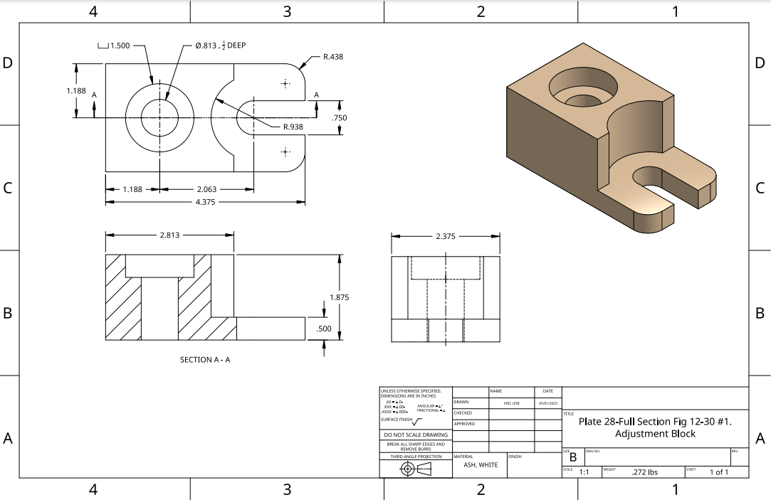
Plate 17 - Fig 12-26 Container Cap-Orthographic Projection with Right Side View as a Full Section with Dimensions
|
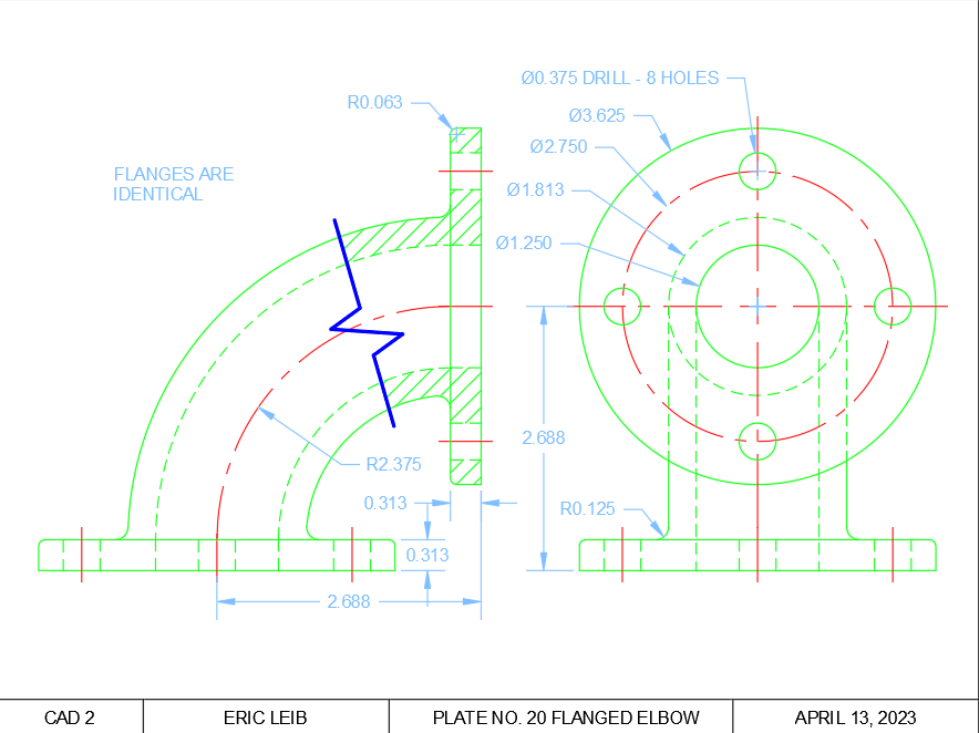
Plate 20 - Fig 12-28 Flanged Elbow-Front & Right Side only with Broken Out Section on Front View with Dimensions
|
OnShape: Multi-View Drawings
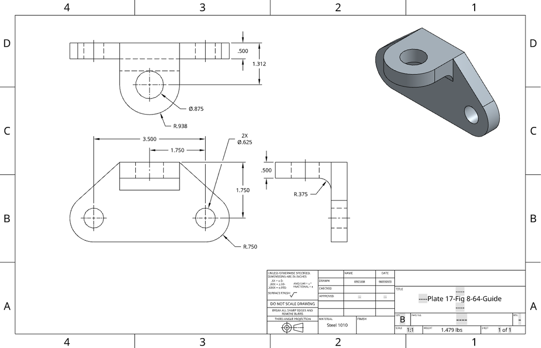
OnShape Plate 17-Fig 8-64-Guide
|
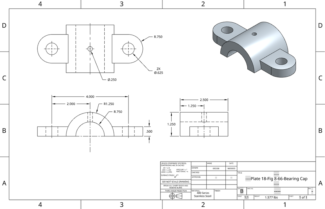
OnShape Plate 18-Fig 8-66-Bearing Cap
|
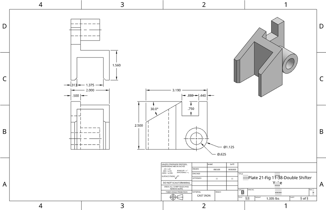
OnShape Plate 21-Fig 11-38-Double Shifter Yoke
|
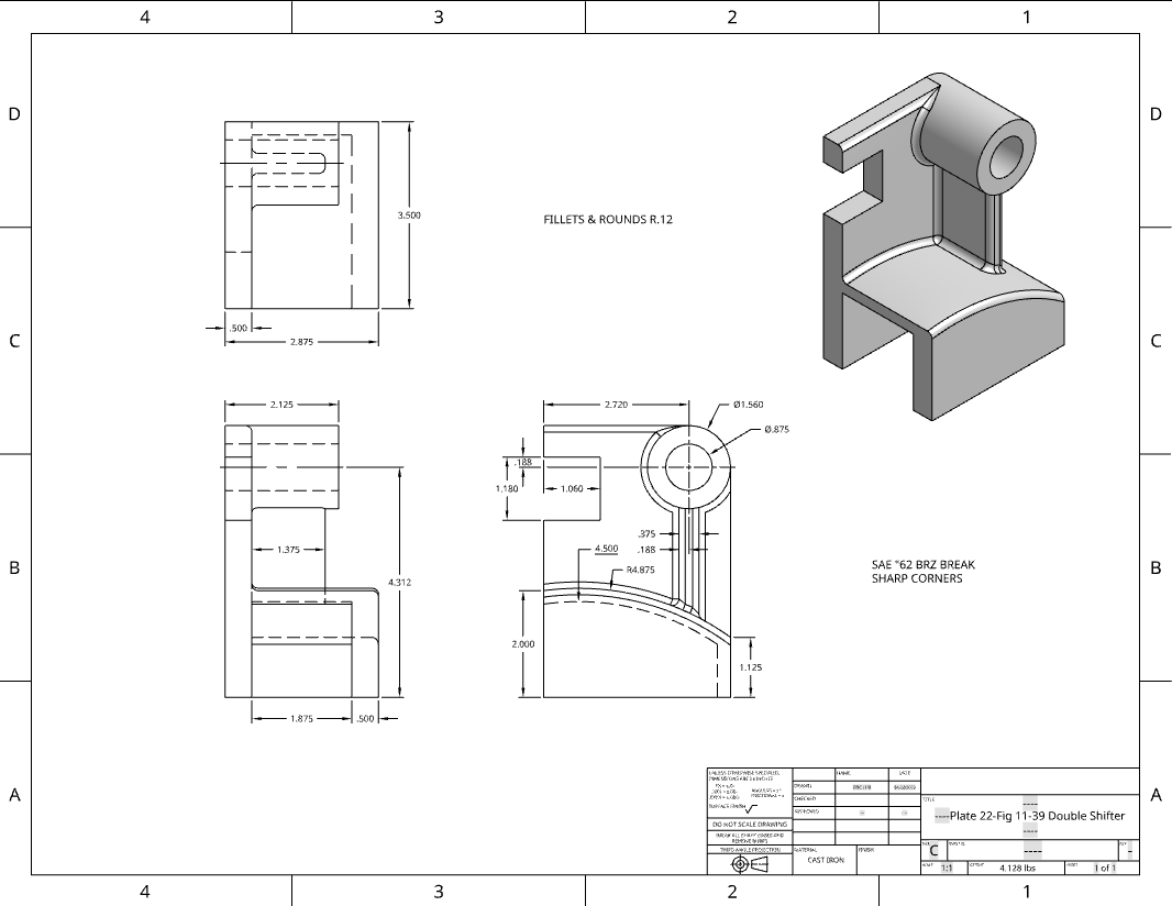
OnShape Plate 22-Fig 11-39 Double Shifter
|
OnShape: Section-View Drawings

|
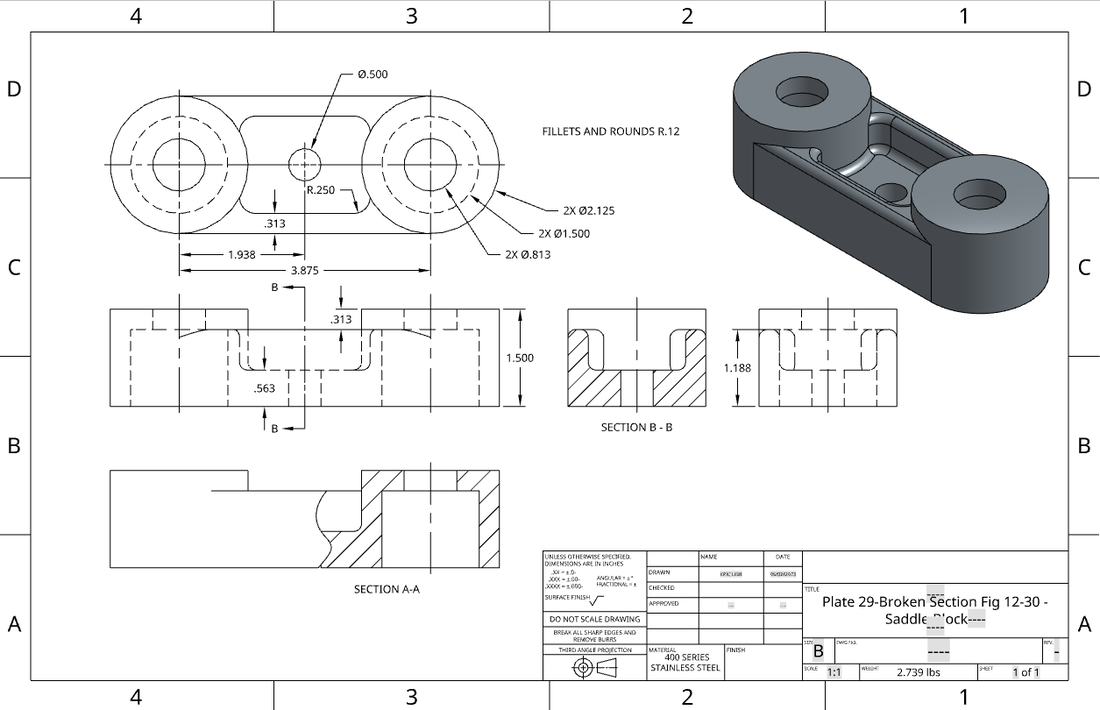
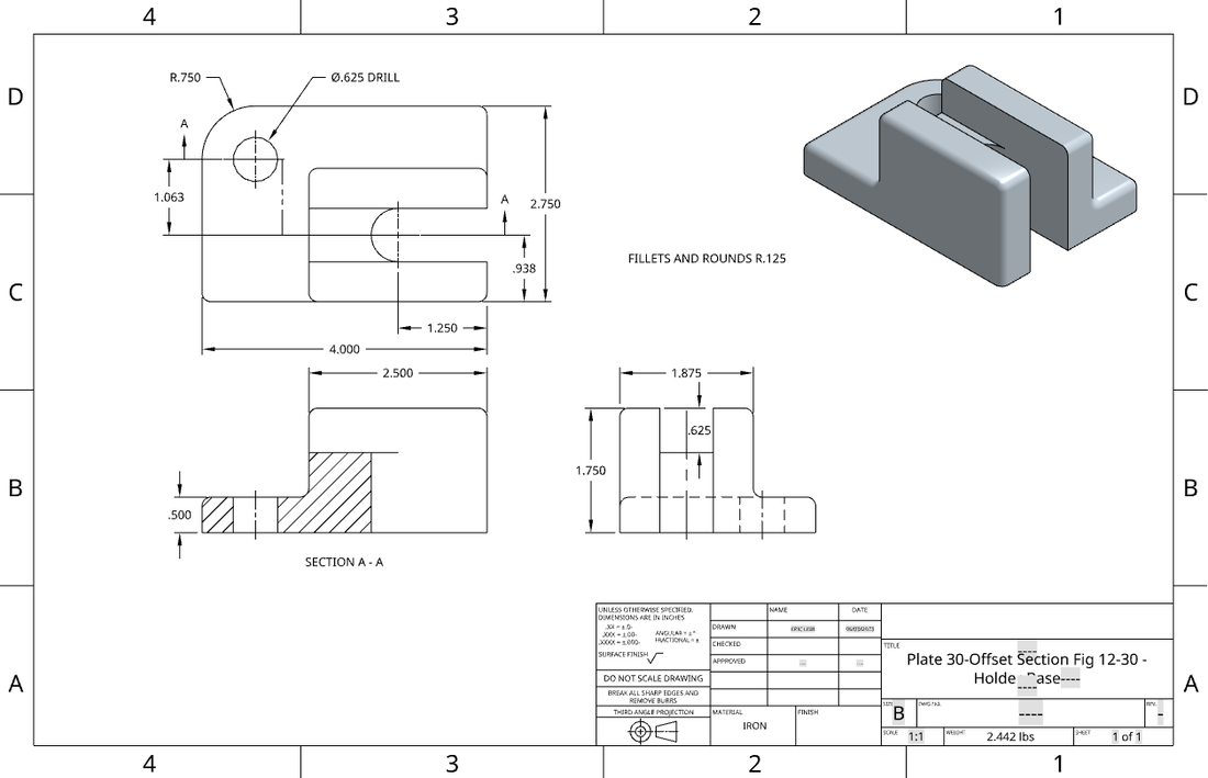
OnShape Plate 28-Full Section Fig 12-30 #1. Adjustment Block OnShape Plate 29-Broken Section Section Fig 12-30 #3. Saddle Block with Broken Section on Front view A-A and Right Side view as a Full Section B-B OnShape Plate 30-Offset Section Fig 12-30 #4. Holder Base |
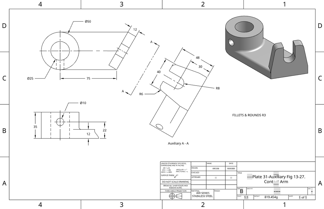
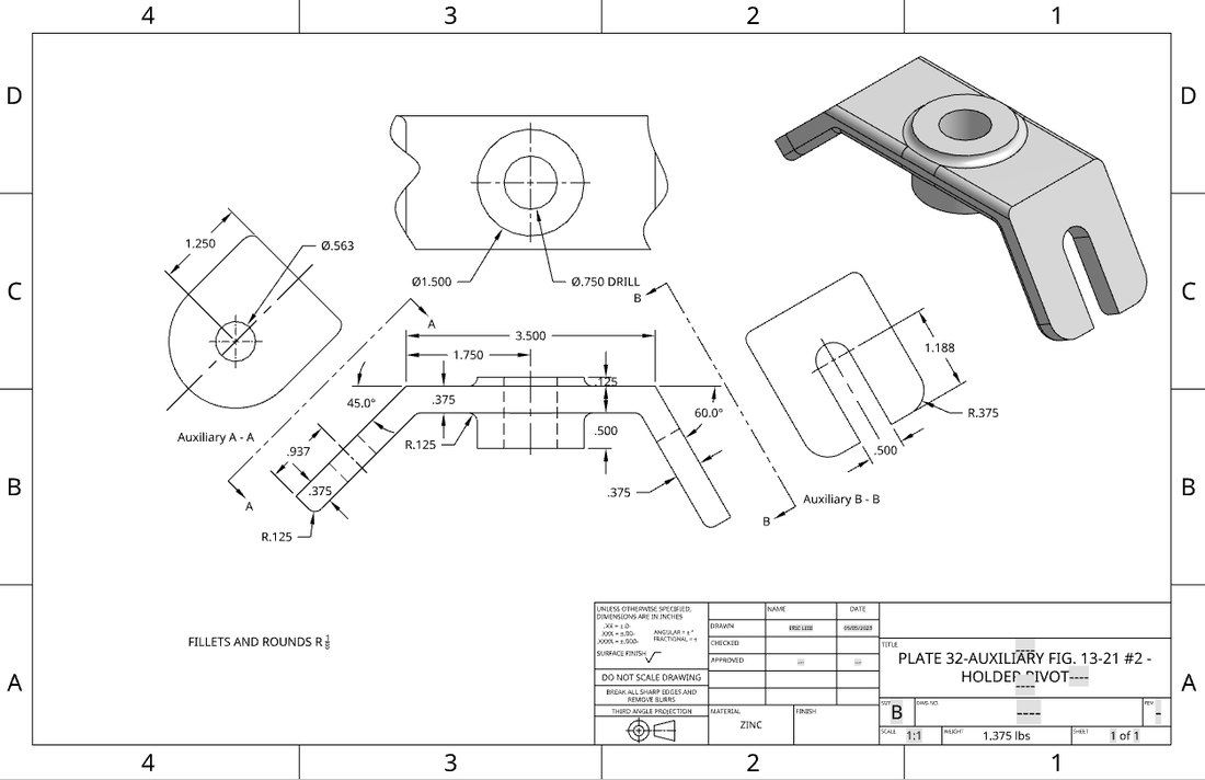
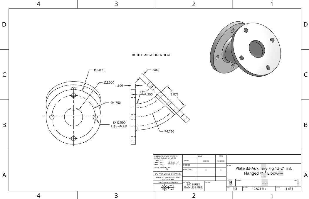
OnShape: Auxiliary-View Drawings
Auxiliary views are a type of orthographic projection used to determine the true size and shape of inclined and oblique surfaces of objects. Normally, auxiliary views are projected from existing, principal views. This concept allowed for us to experience how to accurately dimension a face of an object that cannot initially be dimensioned from a standard orthographic projection view. It also allowed for us to understand that some part faces will not always be perfectly positioned on an x,y,z plane, and how auxiliary views compensate for that issue.
|
OnShape Plate 31-Auxiliary Fig 13-27. Contact Arm. OnShape Plate 32-Auxiliary Fig 13-21 #2. Holder Pivot. OnShape Plate 33-Auxiliary Fig 13-21 #3. Flanged 45° Elbow. |
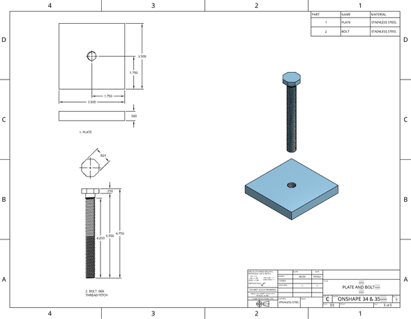
OnShape: Assembly Drawings
An assembly drawing is a presentation of a structure or product with its components connected together in their relative working positions while in use. These components are fabricated separately, and are assembled or installed together at their utility sites such that each part fits and matches with the others. This section of the unit allowed us to understand the complexity and use for assemblies in CAD software, and fathom the importance of not only fabricating multiple parts within one drawing, but accurately and successfully mating them all together in the end.
|
Bolt and Plate Assembly Drawing with Threads |
|
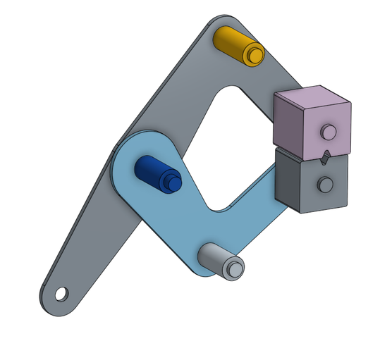
Multi-Part Studio Tutorial: This assembly consisted of 7 different parts all of which came together to accomplish a desired function. The parts include a large and small arm, a large and small arm pin, a large and small arm grip, and pivot pin. |
OnShape Plate 36-Fig 16-35. Caster Exploded Assembly
Manufacturing/Materials Presentation
Conclusion
After taking this course, I have come to find that I have retained countless lessons, skills, and knowledge regarding CAD and its significance in the world of science and engineering. I very much enjoyed the problem-solving aspect that the course provided where I was able to approach numerous obstacles within my work and tackle them my own specific way. Through this, I was able to adapt to the new software systems and improve upon my abilities regarding CAD and mechanical drafting all together. I know with utmost confidence that I will carry this newfound skillset with me throughout college and eventually into my future career. I truly appreciate everything this class has had to offer me and the opportunities it has allowed me to pursue for my own educational benefit.
